- Products
- Global Network
-
Technical
Information- Technical Information Top
-
How to use chip resistors smartly
- 1.Basic knowledge of resistors
- 2.Manufacturing methods and characteristics of thin film resistors
- 3.Performance characteristics of thin film resistors
- 4.High precision and high reliability
- 5.Trimmable chip resistors and altering resistive values
- 6.Application and recommended usage of thin film chip resistors
- 7.Application and recommended usage of small high power thin film ship resistors
- 8.Various methods of current sensing and advantage of current sensing resistors
- 9.Application and recommended usage of current sensing resistors
- Smart usage of High Frequency Chip Components
- Application Information
-
Product Technical Report
Standard Specification for surface mount chip resistors
- Recommended land patterns
- Recommended reflow and flow soldering profile
- Dimensions of the packaging reel
- Dimensions of the packaging tape
Standard Specification for High frequency surface mount components
- Recommended reflow soldering profile
- Dimensions of the packaging tape
- Dimensions of the packaging reel
-
Technical FAQ
High Precision Thin Film Chip Resistors
- ・Part numbering
- ・Performance characteristics
- ・Quality, reliability
- ・Mounting, packaging
Current sensing chip resistors
- ・Part numbering
- ・Performance characteristics
- ・Quality, reliability
- ・Mounting, packaging
- Company Profile
-
QC and Environmental
Activities
- HOME
- Product Information
- Current sensing surface mount resistors
- RL series (short-side terminal)
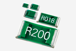
Current sensing surface mount resistors
Low resistance resistors with short side terminal.
Low resistance chip resistors (short-side terminal) RL series
- Lead free ※
- Halogen free
- RoHS Compliance
- High Precision
- AEC-Q200 Compliant
- Large current sensing
- Wide operating temperature range
- Low EMF
- jumper
-
-
※Please contact us for more information or if you cannot find what you are looking for such as equivalent products for old part number
-
RL - Contents
RL - Features & Applications
Features
- Innovative structure that takes consideration of heat dissipation suppress the surface temperature enabling the small sizes reducing the influence of heat on surrounding components.
Applications
- PC power sources, inverters, automotive electronics, adopters, industrial machines

RL - Specifications
◆Part numbering system

◆Electrical Specification
| Type | Power ratings |
Temperature coefficient of resistance |
Resistance range(Ω) Resistance tolerance | Maximum voltage |
Resistance value series |
Operating temperature |
Packaging quantity |
||||||
|---|---|---|---|---|---|---|---|---|---|---|---|---|---|
| (ppm/℃) | ±1%(F) | ±2%(G) | ±5%(J) | ||||||||||
| RL0510 | 1/8W | 0 ~ +350(T) | 50m≦R<100m | ー | √(P・R) | E-24 | -55℃ ~ 125℃ |
10,000pcs | |||||
| 1/6W | 0 ~ +200(S) | 100m≦R≦4.7 | ー | ||||||||||
| 5.1≦R≦47 | |||||||||||||
| RL0816 | 1/4W | 0 ~ +200(S) | 20m≦R<100m | 5,000pcs | |||||||||
| 0 ~ +350(T) | |||||||||||||
| 1/5W | 0 ~ +100(R) | 100m≦R≦6.8 | ー | ||||||||||
| 0 ~ +200(S) | |||||||||||||
| 7.5≦R≦68 | |||||||||||||
| RL1220 | 1/4W | 0 ~ +200(S) | 43m≦91m | ||||||||||
| 0 ~ +350(T) | |||||||||||||
| 10m≦91m | |||||||||||||
| 1/3W | 0 ~ +100(R) | 100m≦R≦10 | |||||||||||
| 0 ~ +200(S) | |||||||||||||
| 11≦R≦100 | |||||||||||||
| RL1632 | 1/2W | 0 ~ +100(R) | 510m≦R≦4.7*1 | 56m≦R≦470m | ー | ー | T1 T5 |
||||||
| 0 ~ +200(S) | ー | 33m≦R≦51m | |||||||||||
| 0 ~ +350(T) | 27m≦R≦30m | 18m≦R≦24m | |||||||||||
| 0 ~ +500(T) | ー | 10m≦R≦16m | |||||||||||
*1 RL series with resistance tolerance 0.5% is also available. Please contact our sales office.
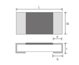
◆Dimensions

| Type | Size (inch) |
L | W | a | b | t | |
|---|---|---|---|---|---|---|---|
| RL0510 | R≦0.2Ω | 0402 | 1.00±0.05 | 0.50±0.05 | 0.15±0.10 | 0.25±0.10 | 0.35+0.15/-0.10 |
| R>0.2Ω | 0.15±0.10 | 0.35±0.10 | |||||
| RL0816 | R≦0.082Ω | 0603 | 1.60±0.20 | 0.80±0.20 | 0.20±0.15 | 0.25±0.20 | 0.45+0.15/-0.10 |
| R>0.091Ω | 0.20±0.15 | 0.45±0.10 | |||||
| RL1220 | R≦0.068Ω | 0805 | 2.00±0.20 | 1.25±0.20 | 0.40±0.20 | 0.40±0.20 | 0.50±0.20 |
| R>0.075Ω | 0.40±0.10 | ||||||
| RL1632 | 1206 | 3.20±0.20 | 1.60±0.20 | ー | 1.00±0.15 | 0.50±0.15 | |
(unit:mm)
◆Derating Curve

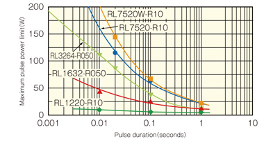
◆Resistance to pulse power

Test procedure
Voltage pulse is applied to the test samples mounted
on the test board.
After each pulse, resistance drift is measured. Pulse
voltage is increased until the drift exceeds +/-0.5%.
The power at that voltage is defined as the maximum
pulse power
Please feel free to contact us about products,
requesting documents and samples.
Products
-
-
Thin film surface mount resistors
- Thin film surface mount resistors TOP
- HRG series
- MRG series
- NRG series
- PRG series
- RG series
- RGA series
- RGT series
- RGV series
- RM series
- RMA series
- RR series
- RS series
- RT series
- URG series
- Current sensing surface mount resistors TOP
- KRL series (4 terminal type)
- KRL series (long-side terminal)
- KRL series (short-side terminal)
- PRL/RL series (long-side terminal)
- RL series (short-side terminal)
- YJP series
- High freguency surface mount components TOP
- ATF series
- ATS-FD series
- HPT series
- P*V series
- PAT series
- PAT series, W type
- PCS series
- PS series
- RFD series
-
Thin film surface mount resistors
Activity Contents
Technical Information
How to use chip resistors smartly
- 1.Basic knowledge of resistors
- 2.Manufacturing methods and characteristics of thin film resistors
- 3.Performance characteristics of thin film resistors
- 4.High precision and high reliability
- 5.Trimmable chip resistors and altering resistive values
- 6.Application and recommended usage of thin film chip resistors
- 7.Application and recommended usage of small high power thin film ship resistors
Standard Specification for surface mount chip resistors
- Recommended land patterns
- Recommended reflow and flow soldering profile
- Dimensions of the packaging reel
- Dimensions of the packaging tape
Standard Specification for High frequency surface mount components
Smart usage of High Frequency Chip Components
Susumu Deutschland GmbH


