- Products
- Global Network
-
Technical
Information- Technical Information Top
-
How to use chip resistors smartly
- 1.Basic knowledge of resistors
- 2.Manufacturing methods and characteristics of thin film resistors
- 3.Performance characteristics of thin film resistors
- 4.High precision and high reliability
- 5.Trimmable chip resistors and altering resistive values
- 6.Application and recommended usage of thin film chip resistors
- 7.Application and recommended usage of small high power thin film ship resistors
- 8.Various methods of current sensing and advantage of current sensing resistors
- 9.Application and recommended usage of current sensing resistors
- Smart usage of High Frequency Chip Components
- Application Information
-
Product Technical Report
Standard Specification for surface mount chip resistors
- Recommended land patterns
- Recommended reflow and flow soldering profile
- Dimensions of the packaging reel
- Dimensions of the packaging tape
Standard Specification for High frequency surface mount components
- Recommended reflow soldering profile
- Dimensions of the packaging tape
- Dimensions of the packaging reel
-
Technical FAQ
High Precision Thin Film Chip Resistors
- ・Part numbering
- ・Performance characteristics
- ・Quality, reliability
- ・Mounting, packaging
Current sensing chip resistors
- ・Part numbering
- ・Performance characteristics
- ・Quality, reliability
- ・Mounting, packaging
- Company Profile
-
QC and Environmental
Activities
- HOME
- Product Information
- High frequency surface mount components
- PAT series, W type
High frequency surface mount components
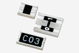
Chip attenuators with wider frequency range
Precision chip attenuators (W type) PAT-W series
- Lead free
- Halogen free
- RoHS Compliance
PAT-W - Contents
※Since the land pattern differs for each series, it is described in the PDF catalogue for each series
PAT-W - Features & Applications
Features
- Single attenuating element realizes excellent attenuating characteristics
- Wide frequency range makes it possible to handle circuits with different frequency with ease
- The distribution of the terminals, signal terminals in the middle and ground terminal at ends, are designed for easy integration to coaxial connectors
Applications
- Attenuator for coaxial lines/circuit
- Attenuator for measuring instrumentation

PAT-W - Specifications
◆Part numbering system

◆Electrical Specification
| Type | PAT3042 | PAT4556 | PAT3060H |
|---|---|---|---|
| Attenuation | 0-10(1dB step), 16,20dB | 0-10(1dB step), 13,16,20dB | 1,2,3,5,6,10dB |
| Attenuation tolerance | Refer table1 | ±0.5dB | |
| Impedance | 50Ω(C) | 50Ω(C) | 50Ω(C) |
| VSWR | <1.1(DC-2GHz) <1.2(2-5GHz), <1.3(5-10GHz) |
<1.2 | |
| Operating frequency | DC~10GHz | DC~6GHz | |
| Rated power | 250mW | 500mW | 5W |
| Rated operating temperature |
70℃ | ||
| Operating temperature | -55℃~+125℃ | ||
| Packaging quantity | 50pcs/bag(B) 1,000pcs/reel(T1) 2,000pcs/reel(T2) |
50pcs/bag(B) 1,000pcs/reel(T1) |
100pcs/bag(B) 1,000pcs/reel(T1) |
| Attenuation tolerance | ||||
| Attenuuation* | Rank | DC~2GHz | 2~5GHz | 5~10GHz |
|---|---|---|---|---|
| 0~10dB | A | ±0.1dB | ±0.2dB | ±0.4dB |
| 0~10dB | B | ±0.2dB | ±0.3dB | ±0.5dB |
| 16, 20dB (13dB)** |
B | ±0.2dB | ±0.3dB | ±0.5dB |
* : Applicable products: PAT3042 and PAT4556
** : Applicable product is only PAT4556
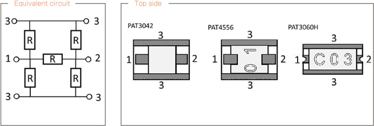
◆Equivalent Circuit and pin arrangement

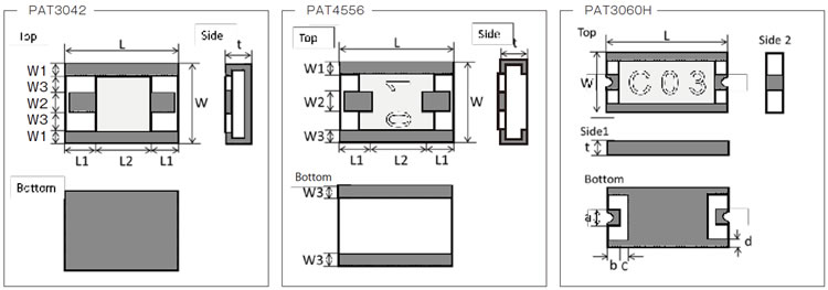
◆Dimensions

| Type | PAT3042 | |||||
|---|---|---|---|---|---|---|
| Size(inch) | 1612 | |||||
| Symbol | 0dB | 1dB | 2,3dB | 4,5,6dB | 7,8,9,10dB | 16,20dB |
| L | 4.2±0.20 | |||||
| W | 3.0±0.20 | |||||
| t | 0.8±0.15 | |||||
| W1 | 0.40±0.15 | 0.30±0.15 | 0.40±0.15 | |||
| W2 | 0.66±0.10 | 0.66±0.10 | 0.90±0.10 | |||
| W3 | 0.77±0.10 | 0.85±0.10 | 0.65±0.10 | |||
| L1 | ー | 1.90±0.20 | 1.90±0.20 | 1.75±0.20 | 1.60±0.20 | 1.15±0.20 |
| L2 | 4.20±0.20 | 0.30±0.20 | 0.30±0.20 | 0.60±0.20 | 0.90±0.20 | 1.80±0.20 |
(unit:mm)
| Type | PAT4556 | |
| Size(inch) | 2218 | |
|---|---|---|
| Symbol | 0dB | 1 ~ 20dB |
| L | 5.60±0.20 | |
| W | 4.50±0.20 | |
| t | 0.80±0.15 | |
| W1 | 0.60±0.10 | |
| W2 | 0.64±0.10 | 1.3±0.10 |
| W3 | 0.60±0.10 | |
(unit:mm)
| Type | PAT3060H |
| Size(inch) | 2412 |
|---|---|
| L | 6.00±0.20 |
| W | 3.00±0.20 |
| t | 0.70±0.15 |
| a | 0.80±0.15 |
| b | 0.45±0.10 |
| c | 0.50±0.10 |
| d | max 0.5 |
(unit:mm)
※Detailed information other than the above is described in PDF.
Please feel free to contact us about products,
requesting documents and samples.
Products
-
-
Thin film surface mount resistors
- Thin film surface mount resistors TOP
- HRG series
- MRG series
- NRG series
- PRG series
- RG series
- RGA series
- RGT series
- RGV series
- RM series
- RMA series
- RR series
- RS series
- RT series
- URG series
- Current sensing surface mount resistors TOP
- KRL series (4 terminal type)
- KRL series (long-side terminal)
- KRL series (short-side terminal)
- PRL/RL series (long-side terminal)
- RL series (short-side terminal)
- YJP series
- High freguency surface mount components TOP
- ATF series
- ATS-FD series
- HPT series
- P*V series
- PAT series
- PAT series, W type
- PCS series
- PS series
- RFD series
-
Thin film surface mount resistors
Activity Contents
Technical Information
How to use chip resistors smartly
- 1.Basic knowledge of resistors
- 2.Manufacturing methods and characteristics of thin film resistors
- 3.Performance characteristics of thin film resistors
- 4.High precision and high reliability
- 5.Trimmable chip resistors and altering resistive values
- 6.Application and recommended usage of thin film chip resistors
- 7.Application and recommended usage of small high power thin film ship resistors
Standard Specification for surface mount chip resistors
- Recommended land patterns
- Recommended reflow and flow soldering profile
- Dimensions of the packaging reel
- Dimensions of the packaging tape
Standard Specification for High frequency surface mount components
Smart usage of High Frequency Chip Components
Susumu Deutschland GmbH


