- Products
- Global Network
-
Technical
Information- Technical Information Top
-
How to use chip resistors smartly
- 1.Basic knowledge of resistors
- 2.Manufacturing methods and characteristics of thin film resistors
- 3.Performance characteristics of thin film resistors
- 4.High precision and high reliability
- 5.Trimmable chip resistors and altering resistive values
- 6.Application and recommended usage of thin film chip resistors
- 7.Application and recommended usage of small high power thin film ship resistors
- 8.Various methods of current sensing and advantage of current sensing resistors
- 9.Application and recommended usage of current sensing resistors
- Smart usage of High Frequency Chip Components
- Application Information
-
Product Technical Report
Standard Specification for surface mount chip resistors
- Recommended land patterns
- Recommended reflow and flow soldering profile
- Dimensions of the packaging reel
- Dimensions of the packaging tape
Standard Specification for High frequency surface mount components
- Recommended reflow soldering profile
- Dimensions of the packaging tape
- Dimensions of the packaging reel
-
Technical FAQ
High Precision Thin Film Chip Resistors
- ・Part numbering
- ・Performance characteristics
- ・Quality, reliability
- ・Mounting, packaging
Current sensing chip resistors
- ・Part numbering
- ・Performance characteristics
- ・Quality, reliability
- ・Mounting, packaging
- Company Profile
-
QC and Environmental
Activities
Thin film surface mount resistors
High-temperature operation. (Up to 230 degree Celsius)
High temperature thin film chip resistors RGA series AEC-Q200 Compliant
- Lead free
- Halogen free
- RoHS Compliance
- High Reliability
- High Precision
- AEC-Q200 Compliant
- High-temperature operation
- High power
- High voltage
- Anti-surge
- Non-magnetic
- High-Resolution Audio
- Anti-sulfur
- trimmable
- leads
RGA - Contents
RGA - Features & Applications
Features
- Conductive epoxy compatible
- Operating temperature up to 230℃
- Resistance tolerance: ±0.1%, TCR: ±10ppm/℃
- Thin film structure enabling low noise and anti-sulfur
Applications
- Automotive electronics
- Equipment used in high temperature
- Downhole drilling
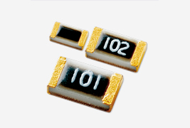
RGA - Specifications
◆Part numbering system

◆Electrical Specification
| Type | Power ratings |
Temperature coefficient of resistance |
Resistance range(Ω) Resistance tolerance |
Maximum voltage |
Resistance value series |
Operating temperature |
Packaging quantity |
|
|---|---|---|---|---|---|---|---|---|
| (ppm/℃) | ±0.1%(B) | ±0.5%(D) | ||||||
| RGA1005 | 1/32W | ±10(N) | 47≦R≦100k | 50V | E-24, E-96 | -55℃ ~ 230℃ | T1 T5 |
|
| ±25(P) | ||||||||
| RGA1608 | 1/16W | ±10(N) | 47≦R≦274k | 100V | ||||
| ±25(P) | 47≦R≦332k | 47≦R≦360k | ||||||
| RGA2012 | 1/10W | ±10(N) | 47≦R≦475k | 150V | ||||
| ±25(P) | 47≦R≦475k | 47≦R≦1M | ||||||
◆Dimensions
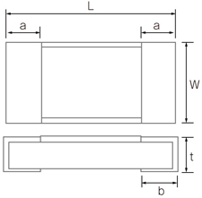
| Type | Size
(inch) |
L | W | a | b | t |
|---|---|---|---|---|---|---|
| RGA1005 | 0402 | 1.00+0.1/-0.05 | 0.50±0.05 | 0.20±0.10 | 0.25±0.05 | 0.35±0.05 |
| RGA1608 | 0603 | 1.60±0.20 | 0.80+0.25/-0.20 | 0.30±0.20 | 0.30±0.20 | 0.40+0.15/-0.10 |
| RGA2012 | 0805 | 2.00±0.20 | 1.25+0.25/-0.20 | 0.40±0.20 | 0.40±0.20 | 0.40+0.15/-0.10 |
(unit:mm)
◆Reliability specification
| Test items | Condition (test methods (MIL-PRF-55342/JIS C5201-1) | Standard |
|---|---|---|
| Short time overload | 2.5 x rated voltage*1, 5seconds | ±(0.1%+0.01Ω) |
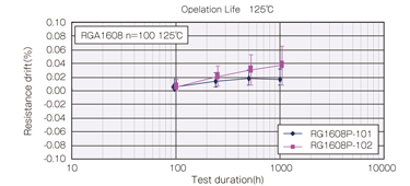
| Life (biased) | 125℃, rated voltage*1, 90min on 30min off, 1000hours | ±(0.2%+0.05Ω) |
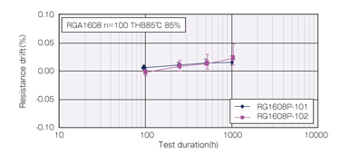
| High temperature high humidity | 85℃, 85%RH, 1/10 of rated power, 90min on 30min off, 1000hours | ±(0.2%+0.01Ω) |
| Temperature shock | -55℃(30min) ~ 125℃(30min) 1000cycles | ±(0.2%+0.01Ω) |
| High temperature exposure | 155℃, no bias, 1000hours | ±(0.2%+0.05Ω) |
| Vibration | Frequency 10Hz ~ 500Hz, vibration amplitude 1.5mm or acceleration 10gn test duration for each of 3 axis: 6 hours |
±(0.2%+0.05Ω) |
| Resistance to soldering heat | 260±5℃, 10 seconds (reflow) | ±(0.5%+0.01Ω) |
*1 Rated voltage is given by E= √R x P
E= rated voltage(V), R=nominal resistance value(Ω), P=rated power(W)
If rated voltage exceeds maximum voltage /element, maximum voltage/element is the rated voltage.
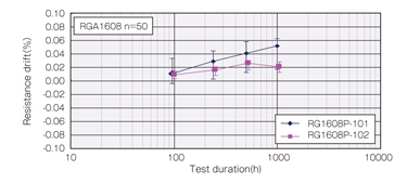
◆Reliability test data
○Biased life test
○High temperature high humidity (biased)
○Temperature shock
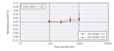
○High temperature exposure
◆Derating Curve

Please feel free to contact us about products,
requesting documents and samples.
Products
-
-
Thin film surface mount resistors
- Thin film surface mount resistors TOP
- HRG series
- MRG series
- NRG series
- PRG series
- RG series
- RGA series
- RGT series
- RGV series
- RM series
- RMA series
- RR series
- RS series
- RT series
- URG series
- Current sensing surface mount resistors TOP
- KRL series (4 terminal type)
- KRL series (long-side terminal)
- KRL series (short-side terminal)
- PRL/RL series (long-side terminal)
- RL series (short-side terminal)
- YJP series
- High freguency surface mount components TOP
- ATF series
- ATS-FD series
- HPT series
- P*V series
- PAT series
- PAT series, W type
- PCS series
- PS series
- RFD series
-
Thin film surface mount resistors
Activity Contents
Technical Information
How to use chip resistors smartly
- 1.Basic knowledge of resistors
- 2.Manufacturing methods and characteristics of thin film resistors
- 3.Performance characteristics of thin film resistors
- 4.High precision and high reliability
- 5.Trimmable chip resistors and altering resistive values
- 6.Application and recommended usage of thin film chip resistors
- 7.Application and recommended usage of small high power thin film ship resistors
Standard Specification for surface mount chip resistors
- Recommended land patterns
- Recommended reflow and flow soldering profile
- Dimensions of the packaging reel
- Dimensions of the packaging tape
Standard Specification for High frequency surface mount components
Smart usage of High Frequency Chip Components
Susumu Deutschland GmbH


