-Specialist in Thin Film Technology-
Susumu Deutschland GmbH6.Application and recommended usage of thin film chip resistors
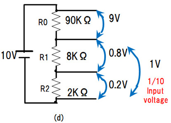
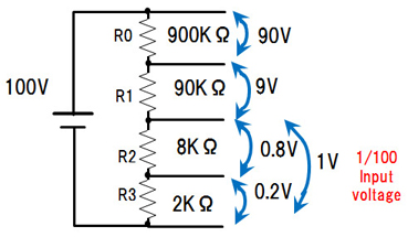
6.1 Voltage dividers
・Voltage dividers, shown below, are circuits with series of resistors to divide high voltage into smaller voltage. Input voltage is divided in the ratio of the resistance.
・Precision resistors are required because the tolerance and TCR of the resistors directly influence the divided voltage.
| ・Application examples | : | Power supply, Reference voltage generator, Battery control (high voltage control of automotive) |
| ・Recommended products: |
URG series, RG series, RM series, MRG series(anti-surge), LRG series(leaded) |
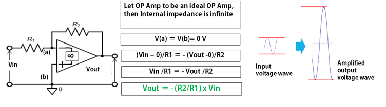
6.2 Amplification by operational amplifier
・Small signals are amplified by operational amplifier and precision resistors as shown below
・Input signal is so small that it requires low noise, precision resistors
・In order to get precise amplification ratio, R1 / R2 it is important for both of these resistors to have closely related tolerance and TCR (relative tolerance and TCR)
| ・Application examples | : | Sensor module(automotive, IoT), Test and measurement instrument, Medical electronics instrument. |
| ・Recommended products | : |
URG series, RG series, RM series , MRG series(anti-surge), LRG series(leaded) Relative tolerance and TCR of multiple resistors are specified in RM series(network resistors) only. |
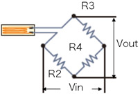
6.3 Strain gauge (resistor bridge circuits)
・Strain gauge is a sensor that detect the amount of strain or pressure by change of resistance. Basic circuit is shown below.
・The change of resistance is calculated by measured voltage and resistance (formula (2))
R1(gauge)
An example of strain gauge circuit
Initial value
R1 = R2
if
R3 = R4
Vout = 0 V
When gauge is strained, R1 changes
R1 = R2 + ΔR
ΔR:change
Vout is given by (1)
Vout = Vin{R3/( R1+R3)-R4/(R2+R4)}—(1)
R1 = R2 + ΔR 、R3 = R4
Then, you get ΔR as shown below (2)
ΔR =Vout(R2+R4)²/{R4-Vout(R2 +R4)}—(2)
ΔR, amount of strain, is calculated by output voltage
| ・Application | : | Strain gauge, Pressure sensor, Flow sensor including gas sensor for automobile, etc. |
| ・Recommended products | : |
URG series, RG series, RM series, MRG series(anti-surge), LRG series(leaded) Relative tolerance and TCR of multiple resistors are specified in RM series(network resistors) only. |
Technical Information
-
- 1.Basic knowledge of resistors
- 2.Manufacturing methods and characteristics of thin film resistors
- 3.Performance characteristics of thin film resistors
- 4.High precision and high reliability
- 5.Trimmable chip resistors and altering resistive values
- 6.Application and recommended usage of thin film chip resistors
- 7.Application and recommended usage of small high power thin film ship resistors
- 8.Various methods of current sensing and advantage of current sensing resistors
- 9.Application and recommended usage of current sensing resistors
-
-
Please feel free to contact us about products,
requesting documents and samples.
Susumu Deutschland GmbH
![]()