-Specialist in Thin Film Technology-
Susumu Deutschland GmbHThin film surface mount resistors
High-power with long side terminal
High power thin film chip resistors(long side terminal) PRG series AEC-Q200 Compliant
- Lead free
- Halogen free
- RoHS Compliance
- High Reliability
- High Precision
- AEC-Q200 Compliant
- High-temperature operation
- High power
- High voltage
- Anti-surge
- Non-magnetic
- High-Resolution Audio
- Anti-sulfur
- trimmable
- leads
-
-
※Please contact us for more information or if you cannot find what you are looking for such as equivalent products for old part number
-
PRG - Contents
PRG - Features & Applications
Features
- Long side terminal enabling higher power capability
- Significantly larger power handling capability than conventional same size resistors
Size: 3216 ~ 6432, power ratings: 0.5 ~ 3.0W, Resistance range: 2.5 ~ 250KΩ - Precision resistance tolerance: ±0.1%, very small TCR: ±25ppm/℃
- Thin film structure enabling low noise and anti-sulfur
Applications
- Automotive electronics
- DC motor, inverters
- Robotics, Industrial control system

PRG - Specifications
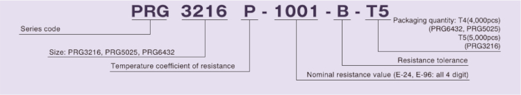
◆Part numbering system
◆Electrical Specification
| Type | Power ratings |
Temperature coefficient of resistance |
Resistance range(Ω) Resistance tolerance |
Maximum voltage |
Resistance value series |
Operating temperature |
Packaging quantity |
|
|---|---|---|---|---|---|---|---|---|
| (ppm/℃) | ±0.1%(B) | ±0.5%(D) | ||||||
| PRG3216 | 1.0W | ±25(P) | 47≦R≦100k | 10≦R≦100k | 150V | E-24, E-96 | -55℃ ~ 155℃ | T5 |
| ±50(Q) | 2.5≦R≦100k | |||||||
| PRG5025 | 1.5W ~ 2.0W | ±25(P) | 47≦R≦200k | 10≦R≦200k | 200V | T4 | ||
| ±50(Q) | 2.5≦R≦200k | |||||||
| PRG6432 | 2.0W ~ 3.0W | ±25(P) | 47≦R≦250k | 10≦R≦250k | 400V | |||
| ±50(Q) | 2.5≦R≦250k | |||||||
◆Dimensions
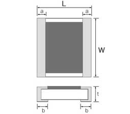
| Type | Size (inch) |
W | L | a | b | t |
|---|---|---|---|---|---|---|
| PRG3216 | 1206 | 3.20+0.40/-0.20 | 1.60±0.20 | 0.30±0.20 | 0.35±0.20 | 0.45+0.15/-0.10 |
| PRG5025 | 2010 | 5.00±0.20 | 2.50±0.20 | 0.55±0.20 | 0.60±0.20 | 0.45+0.15/-0.10 |
| PRG6432 | 2512 | 6.40+0.20/-0.40 | 3.20±0.20 | 0.40±0.20 | 0.55±0.20 | 0.45+0.15/-0.10 |
(unit:mm)
◆Reliability specification
| Standard | |||
|---|---|---|---|
| Test items | Condition (test methods (JIS C5201-1) | ≦47Ω | ≧47Ω |
| Life (biased) | 70℃, rated voltage*1, 90min on 30min off, 1000hours | ±(0.25%+0.05Ω) | ±(0.1%+0.01Ω) |
| High temperature high humidity | 85℃, 85%RH, 1/10 of rated power, 90min on 30min off, 1000hours | ±(0.25%+0.05Ω) | ±(0.1%+0.01Ω) |
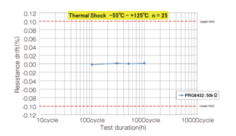
| Temperature shock | -55℃(30min) ~ 125℃(30min) 1000cycles | ±(0.25%+0.05Ω) | ±(0.1%+0.01Ω) |
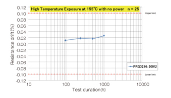
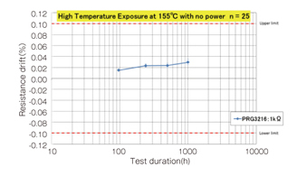
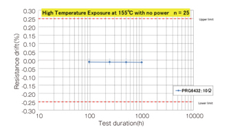
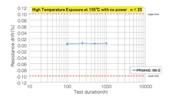
| High temperature exposure | 155℃, no bias, 1000hours | ±(0.25%+0.05Ω) | ±(0.1%+0.01Ω) |
| Resistance to soldering heat | 260±5℃, 10 seconds (reflow) | ±(0.1%+0.01Ω) | ±(0.05%+0.01Ω) |
*1 Rated voltage is given by E= √R x P
E= rated voltage(V), R=nominal resistance value(Ω), P=rated power(W)
If rated voltage exceeds maximum voltage /element, maximum voltage/element is the rated voltage.
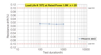
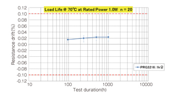
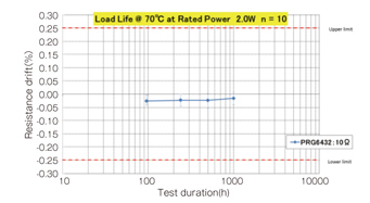
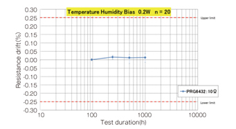
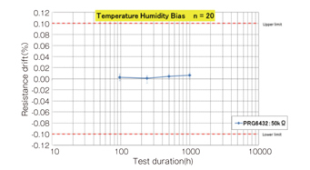
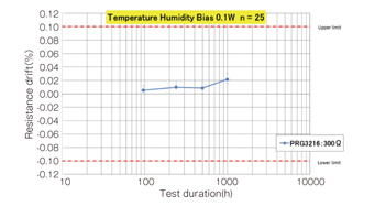
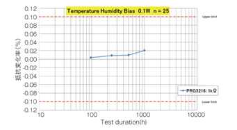
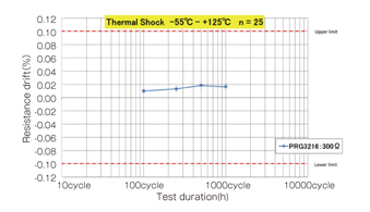
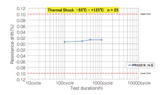
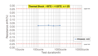
◆Reliability test data
○Biased life test
○High temperature high humidity (biased)
○Temperature shock
○High temperature exposure
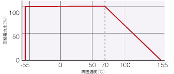
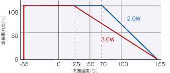
◆Derating Curve
○PRG3216
○PRG6432
Please feel free to contact us about products,
requesting documents and samples.


Susumu Deutschland GmbH
![]()