Susumu Deutschland GmbH

-Specialist in Thin Film Technology-

Susumu Deutschland GmbH
  • Contact
  • Site map
  • Impressum
  • Products
    • Products Top
    • New Products Infomation
    • Selection Guide
    • Product Catalogue
    • Product Category
      • Thin film surface mount resistors
        • HRG series
        • MRG series
        • NRG series
        • PRG series
        • RG series
        • RGA series
        • RGT series
        • RGV series
        • RM series
        • RMA series
        • RR series
        • RS series
        • RT series
        • URG series
      • Current sensing surface mount resistors
        • KRL series (4 terminal type)
        • KRL series (short-side terminal)
        • KRL series (long-side terminal)
        • PRL/RL series (long-side terminal)
        • RL series (short-side terminal)
        • YJP series
      • Metal Alloy Current Sensing Resistors
        • MSR series
        • MSRPF2726 series
        • MSRPF4026 series
        • MSRPM1216 series
        • MSRSF3951 series
      • High-Precision High-Current Alloy Shunt
        • MBRAS series
        • MBRRC series
      • Power choke coils
        • PCMB series
      • High freguency surface mount components
        • ATF series
        • ATS-FD series
        • HPT series
        • P*V series
        • PAT series
        • PAT series, W type
        • PCS series
        • PS series
        • RFD series
      • Sample kits
        • Sample kits
  • Global Network
    • Global Network Top
    • Electronic Commerce
    • Sales Offices (Overseas)
    • Manufacturing Plants
  • Technical
    Information
    • Technical Information Top
    • How to use chip resistors smartly
      • 1.Basic knowledge of resistors
      • 2.Manufacturing methods and characteristics of thin film resistors
      • 3.Performance characteristics of thin film resistors
      • 4.High precision and high reliability
      • 5.Trimmable chip resistors and altering resistive values
      • 6.Application and recommended usage of thin film chip resistors
      • 7.Application and recommended usage of small high power thin film ship resistors
      • 8.Various methods of current sensing and advantage of current sensing resistors
      • 9.Application and recommended usage of current sensing resistors
    • Smart usage of High Frequency Chip Components
      • 1.Most common high frequency chip: Chip Attenuator
      • 2.Chip Attenuator realized by Thin Film technology
      • 3.Main characteristics of chip attenuators and PAT series
      • 4.Various chip attenuators
      • 5.Chip terminator
    • Application Information
      • 1.Automotive
      • 2.FA/Robot
      • 3.Measuring Instrument/Medical Instrument
      • 4.Consumer equipment
    • Product Technical Report
      • Standard Specification for surface mount chip resistors

      • Recommended land patterns
      • Recommended reflow and flow soldering profile
      • Dimensions of the packaging reel
      • Dimensions of the packaging tape
      • Standard Specification for High frequency surface mount components

      • Recommended reflow soldering profile
      • Dimensions of the packaging tape
      • Dimensions of the packaging reel
    • Technical FAQ
      • High Precision Thin Film Chip Resistors

      • ・Part numbering
      • ・Performance characteristics
      • ・Quality, reliability
      • ・Mounting, packaging
      • Current sensing chip resistors

      • ・Part numbering
      • ・Performance characteristics
      • ・Quality, reliability
      • ・Mounting, packaging
  • Company Profile
    • Company Profile TOP
    • About Susumu
      • Principle
      • Susumu Way
      • Profile
      • Locations
      • Organization
      • Company history
    • Activity Contents
      • Exhibition Activities
  • QC and Environmental
    Activities
    • QC and Environmental Activities TOP
    • QC and Environmental Activities
      • Susumu's 「ISO Certified」
      • Susumu’s Policy on Conflict Minerals
      • Susumu’s Environmental Policy
      • The Materials Used in Our Chip Resistors
      • Our Commitment to RoHS/REACH Compliance
      • Designation of Lead Free Products
  • HOME
  • Technical Information
  • Current sensing chip resistors

Technical FAQ Current sensing chip resistors

Part numbering
Q1 How do part number differs between long side terminal KRL and short side terminal KRL? Is it easy to identify ?
A1 The length of the terminal side is the first 2 (or 3) digit in size designation. For example, long side terminals are 3216, 2012, 11050, short side terminals are 1632, 1220, 5010.
Q2 There is E or D after size designation in KRL part numbers, how are they different ?
A2 They are terminal type designators. D means bottom terminal and E means wrap around terminal.

D Type

E Type

Q3 Is the quantity in packaging designated in a part number? What is the unit for packaging ?
A3 Last 2 digits designate the packaging size. It depends the product series and size. Please refer to catalogue under each series.
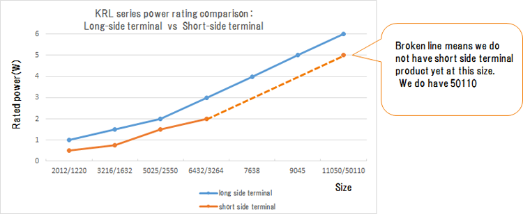
Performance characteristics
Q1 What is the main difference in performance between long side terminal and short side terminal KRL series ?
A1 Long side terminal products dissipates heat better. Therefore, there is a difference in power ratings in the same size long side and short side terminal products.


Q2 KRL series has 2 terminal type and 4 terminal type. How does their performance differ ?
A2 Four terminal type has separate voltage terminals and voltage can be measured more accurately. Land pattern can be simpler for 4 terminal type.
Q3 KRL series has high temperature type and low EMF (Electro motive force)type.
How do we decide which to choose ?
A3 Typically High temp type is chosen because you can use it at higher temperature but if there is a need to control electromotive force (less than 1mV), use low EMF type.
Quality, reliability
Q1 Do KRL series meet automotive reliability ?
A1 It is compliant to automotive electronics standard AEC-Q200. It is widely used for automotive electronics.
Q2 Is any of the current sensing resistor sulfur tolerant ?
A2 None of Susumu's chip resistors use Ag in their terminals. Therefore they are all sulfur tolerant.
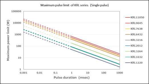
Q3 What is the maximum pulse power limits for KRL series ?
A3 It depends on long side or short side terminal and, product size. Sigle pulse maximum power limit chart is shown here for product series.


The resistance value applicable to the above figure is less than 25 mΩ.
For other resistance values, calculate the limit power by multiplying the graph value by a factor.

Limit power less than 25 mΩ = Figure 1×100%
Limit power greater than 25 mΩ but less than 100 mΩ = Figure 1×50%
Ultra limit power greater than 100 mΩ = Figure 1×20%
*The posted data are reference data, not specification values or guarantee values.
*The wavy lines in the graph are extrapolated estimates.

Mounting, packaging
Q1 Where can I find recommended land patterns for KRL series ?
A1 They are shown in Product technical report. Please be aware that the same size products may have different land pattern in very low resistance products.
Q2 Can they be solder dipped ?
A2 E type can be solder dipped (260oC for 10 seconds). It is not recommended for D type because it does not form solder filets and cannot be examined for soldering quality.
Q3 How much does resistance change by soldering ?
A3 It is specified within +/-0.5% for KRL series.
Q4 Is packaging tape paper or embossed ?
A4 KRL series are packaged in embossed tape. For details, refer to Product technical report.

Technical Information

Technical
Information TOP

How to use chip resistors smartly
  • 1.Basic knowledge of resistors
  • 2.Manufacturing methods and characteristics of thin film resistors
  • 3.Performance characteristics of thin film resistors
  • 4.High precision and high reliability
  • 5.Trimmable chip resistors and altering resistive values
  • 6.Application and recommended usage of thin film chip resistors
  • 7.Application and recommended usage of small high power thin film ship resistors
  • 8.Various methods of current sensing and advantage of current sensing resistors
  • 9.Application and recommended usage of current sensing resistors
Smart usage of
High Frequency
Chip Components
  • 1.Most common high frequency chip: Chip Attenuator
  • 2.Chip Attenuator realized by Thin Film technology
  • 3.Main characteristics of chip attenuators and PAT series
  • 4.Various chip attenuators
  • 5.Chip terminator
Application Information
  • 1. Automotive
  • 2. FA/Robot
  • 3. Measuring Instrument /
    Medical Instrument
  • 4. Consumer equipment
Product Technical Report
  • Standard Specification for surface mount chip resistors
    • Recommended land patterns (soldering footprints)
    • Recommended reflow and flow soldering profile
    • Dimensions of the packaging reel
    • Dimensions of the packaging tape
    Standard Specification for High frequency surface mount components
    • Recommended reflow soldering profile
    • Dimensions of the packaging reel
    • Dimensions of the packaging tape
Technical FAQ
  • High Precision Thin Film Chip Resistors
    • Part numbering
    • Performance characteristics
    • Quality, reliability
    • Mounting, packaging
    Current sensing chip resistors
    • Part numbering
    • Performance characteristics
    • Quality, reliability
    • Mounting, packaging

Contact

Please feel free to contact us about products,
requesting documents and samples.

Contact

  • Sales offices
Page Top

Products

  • New Products
  • Selection guide
  • Product Catalogue

Global Network

  • Word Base
  • Manufacturing Centers
  • Electronic Commerce

Company Profile

About Susumu

  • Principle
  • Susumu Way
  • Profile
  • Locations
  • Organization
  • Company history

Activity Contents

  • Exhibition Activities

Technical Information

How to use chip resistors smartly

  • 1.Basic knowledge of resistors
  • 2.Manufacturing methods and characteristics of thin film resistors
  • 3.Performance characteristics of thin film resistors
  • 4.High precision and high reliability
  • 5.Trimmable chip resistors and altering resistive values
  • 6.Application and recommended usage of thin film chip resistors
  • 7.Application and recommended usage of small high power thin film ship resistors
  • 8.Various methods of current sensing and advantage of current sensing resistors
  • 9.Application and recommended usage of current sensing resistors

Application Information

  • 1.Automotive
  • 2.FA/Robot
  • 3.Measuring Instrument/Medical Instrument
  • 4.Consumer equipment

Standard Specification for surface mount chip resistors

  • Recommended land patterns
  • Recommended reflow and flow soldering profile
  • Dimensions of the packaging reel
  • Dimensions of the packaging tape

Standard Specification for High frequency surface mount components

  • Recommended reflow soldering profile
  • Dimensions of the packaging tape
  • Dimensions of the packaging reel

Smart usage of High Frequency Chip Components

  • 1.Most common high frequency chip: Chip Attenuator
  • 2.Chip Attenuator realized by Thin Film technology
  • 3.Main characteristics of chip attenuators and PAT series
  • 4.Various chip attenuators
  • 5.Chip terminator

Technical FAQ

  • High Precision Thin Film Chip Resistors
  • Current sensing chip resistors

QC and Environmental Activities

  • Susumu's 「ISO Certified」
  • Susumu’s Policy on Conflict Minerals
  • Environmental Policy
  • The materials used in our chip resistors
  • Our Commitment to RoHS/REACH Compliance
  • Designation of lead free products

Privacy Policy | Site map | Contact

Susumu Deutschland GmbH
Susumu Thin Film Specialist and Innovator