-Specialist in Thin Film Technology-
Susumu Deutschland GmbH5.Trimmable chip resistors and altering resistive values
5.1 The structure of trimmable chip resistors and how they work
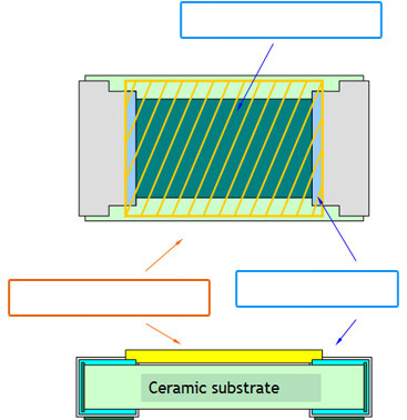
Thin film resistor
Glass film(CVDed)
Terminal film
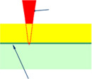
YAG laser
Glass film
Substrate
Thin film resistor
YAG laser applies energy to the thin film resistive element without damaging the glass film
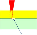
Oxidized film
(translucent)
With the energy, the metal film acquires oxygen from the glass and change itself to metal oxide. Metal resistive film becomes insulator and trimming is done.
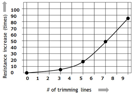
5.2 Adjusting resistor in trimmable chip resistors
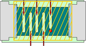
Trimming (conceptual drawing)
This is one example. Actual resistance change depends on products and trimming machines.
Trimmable chip resistors features:
- 1.One trimmable chip can be trimmed into wide range of resistive values
- 2.Glass protective layer stays intact and continues protecting resistors after trimming
- 3.Metal to metal oxide change by trimming makes it possible to adjust precisely.
- 4.The characteristics of metal thin film resistors remain after trimming.
Technical Information
-
- 1.Basic knowledge of resistors
- 2.Manufacturing methods and characteristics of thin film resistors
- 3.Performance characteristics of thin film resistors
- 4.High precision and high reliability
- 5.Trimmable chip resistors and altering resistive values
- 6.Application and recommended usage of thin film chip resistors
- 7.Application and recommended usage of small high power thin film ship resistors
- 8.Various methods of current sensing and advantage of current sensing resistors
- 9.Application and recommended usage of current sensing resistors
-
-
Please feel free to contact us about products,
requesting documents and samples.
Susumu Deutschland GmbH
![]()