-Specialist in Thin Film Technology-
Susumu Deutschland GmbH1.Basic knowledge of resistors
1.1 Resistors and Ohm’s law (how resistors function in circuits)
Typical passive components
- ・Resistors
- ・Capacitors
- ・Inductors (coils)
Ohm’s law is applicable to resistors
Possible usage of resistors under Ohm’s law.
- ・Deciding voltage
- ・Deciding current
- ・Measuring current
- ・Consuming power(converting electricity to heat)

Series or parallel resistors and voltage
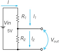
Vout = R2/(R1+R2)
I= Vin/(R1+R2)
I= I1= I2
In series, voltage is proportional to the resistance
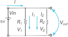
I= I1+ I2
Vout= V2 = V1 = Vin
R1:R2=I2: I1
In parallel, voltage is the same on each resistors
Current is negatively proportional to resistance
1.2 Resistor marking and E series
The resistive value is expressed in 3 or 4 digit numbers following E-series. E-series are geometric progression series and depending on how many numbers used between 1 and 10, they are called E12, E24, and E96 series.
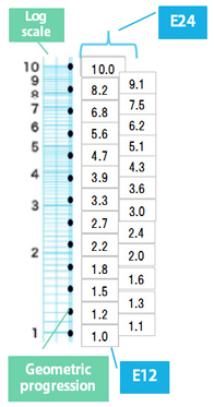
E12 series is a geometric progression
1210n Substitute “n”with 0…11, and you get
1.0, 1.2, 1.5, … 8.2,
12 values with same ratio.
E24 series adds a number in between each of the E12 series, making them 24 numbers. 2410n
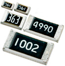
Resistance value is expressed in 3 or 4 digit alpha numeric number on top of the products unless the surface is too small to mark.
⇒Significant figures are expressed in E series.
Additional explanation:Examples of resistance value expression
Chip resistors currently ranges from mΩ(milliohms)to MΩ(mega Ohms). Using the power of 10 and E series, resistance value is expressed as follows. The number of digits changes depending on the size and resistance value(For details, refer to the each product series. E-series are described on page 7 of the catalogue. )
Resistance value range and units

E6, E12, E24 series has 2 significant figures
Last digit is n of 10n
n=1 ⇒101= 10
n=2 ⇒102= 100
n=3 ⇒103= 1000
R means decimal point under 10Ω
E96 series has 3 significant figures
Last digit is n of 10n
n=1 ⇒101= 10
n=2 ⇒102= 100
n=3 ⇒103= 1000
Under 1Ω, numbers after decimal point is expressed in 3 digits after R
3 digit designation
102=> 10 x 100 = 1kΩ
331=> 33 x 10 = 330Ω
3R0=> 3.0 Ω
*Refer to page 7 of the catalogue for 3 digits expression of E96 series
4 digit designation
1002=> 100 x 100 = 10kΩ
4990=> 499 x 1 = 499Ω
3303=> 330 x 1000= 330kΩ
3R00=> 3.0Ω
R220=> 0.22Ω =220mΩ
R005=> 0.005Ω = 5mΩ
Technical Information
-
- 1.Basic knowledge of resistors
- 2.Manufacturing methods and characteristics of thin film resistors
- 3.Performance characteristics of thin film resistors
- 4.High precision and high reliability
- 5.Trimmable chip resistors and altering resistive values
- 6.Application and recommended usage of thin film chip resistors
- 7.Application and recommended usage of small high power thin film ship resistors
- 8.Various methods of current sensing and advantage of current sensing resistors
- 9.Application and recommended usage of current sensing resistors
-
-
Please feel free to contact us about products,
requesting documents and samples.
Susumu Deutschland GmbH
![]()