Susumu Deutschland GmbH

-Specialist in Thin Film Technology-

Susumu Deutschland GmbH
  • Contact
  • Site map
  • Impressum
  • Products
    • Products Top
    • New Products Infomation
    • Selection Guide
    • Product Catalogue
    • Product Category
      • Thin film surface mount resistors
        • HRG series
        • MRG series
        • NRG series
        • PRG series
        • RG series
        • RGA series
        • RGT series
        • RGV series
        • RM series
        • RMA series
        • RR series
        • RS series
        • RT series
        • URG series
      • Current sensing surface mount resistors
        • KRL series (4 terminal type)
        • KRL series (short-side terminal)
        • KRL series (long-side terminal)
        • PRL/RL series (long-side terminal)
        • RL series (short-side terminal)
        • YJP series
      • Metal Alloy Current Sensing Resistors
        • MSR series
        • MSRPF2726 series
        • MSRPF4026 series
        • MSRPM1216 series
        • MSRSF3951 series
      • High-Precision High-Current Alloy Shunt
        • MBRAS series
        • MBRRC series
      • Power choke coils
        • PCMB series
      • High freguency surface mount components
        • ATF series
        • ATS-FD series
        • HPT series
        • P*V series
        • PAT series
        • PAT series, W type
        • PCS series
        • PS series
        • RFD series
      • Sample kits
        • Sample kits
  • Global Network
    • Global Network Top
    • Electronic Commerce
    • Sales Offices (Overseas)
    • Manufacturing Plants
  • Technical
    Information
    • Technical Information Top
    • How to use chip resistors smartly
      • 1.Basic knowledge of resistors
      • 2.Manufacturing methods and characteristics of thin film resistors
      • 3.Performance characteristics of thin film resistors
      • 4.High precision and high reliability
      • 5.Trimmable chip resistors and altering resistive values
      • 6.Application and recommended usage of thin film chip resistors
      • 7.Application and recommended usage of small high power thin film ship resistors
      • 8.Various methods of current sensing and advantage of current sensing resistors
      • 9.Application and recommended usage of current sensing resistors
    • Smart usage of High Frequency Chip Components
      • 1.Most common high frequency chip: Chip Attenuator
      • 2.Chip Attenuator realized by Thin Film technology
      • 3.Main characteristics of chip attenuators and PAT series
      • 4.Various chip attenuators
      • 5.Chip terminator
    • Application Information
      • 1.Automotive
      • 2.FA/Robot
      • 3.Measuring Instrument/Medical Instrument
      • 4.Consumer equipment
    • Product Technical Report
      • Standard Specification for surface mount chip resistors

      • Recommended land patterns
      • Recommended reflow and flow soldering profile
      • Dimensions of the packaging reel
      • Dimensions of the packaging tape
      • Standard Specification for High frequency surface mount components

      • Recommended reflow soldering profile
      • Dimensions of the packaging tape
      • Dimensions of the packaging reel
    • Technical FAQ
      • High Precision Thin Film Chip Resistors

      • ・Part numbering
      • ・Performance characteristics
      • ・Quality, reliability
      • ・Mounting, packaging
      • Current sensing chip resistors

      • ・Part numbering
      • ・Performance characteristics
      • ・Quality, reliability
      • ・Mounting, packaging
  • Company Profile
    • Company Profile TOP
    • About Susumu
      • Principle
      • Susumu Way
      • Profile
      • Locations
      • Organization
      • Company history
    • Activity Contents
      • Exhibition Activities
  • QC and Environmental
    Activities
    • QC and Environmental Activities TOP
    • QC and Environmental Activities
      • Susumu's 「ISO Certified」
      • Susumu’s Policy on Conflict Minerals
      • Susumu’s Environmental Policy
      • The Materials Used in Our Chip Resistors
      • Our Commitment to RoHS/REACH Compliance
      • Designation of Lead Free Products
  • HOME
  • Technical Information
  • 3.Performance characteristics of thin film resistors

3.Performance characteristics of thin film resistors

3.1 Advantage and performance characteristics of Susumu thin film resistors

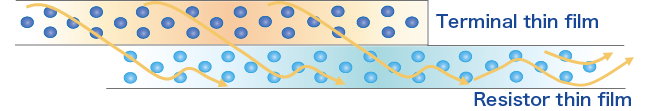
Thin film resistors, made of deposited (such as sputtered) homogeneous metal thin film, have smooth electron flow, small temperature coefficient of resistance, and long term stability and fit for high precision application.

Monolithic structure with smooth electron flow

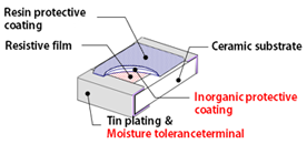
In order to further improve moisture tolerance, our terminals also have innovative thin film structure. Therefore, Susumu’s RG series are extremely robust, reliable and stable and widely used for automotive electronics.

Double layered protective coating
・Inorganic film
Innovative moisture tolerant terminal

3.2 Difference between thin film resistors and thick film resistors

Thin film resistors, due to their continuous even metal structure, compared to thick film resistors, have smaller resistance tolerance and temperature coefficient of resistance (TCR)

Performance Typical thick film resistors Susumu thin film resistors
Resistive tolerance +/- 0.5%, 1%
(precision)
+/-0.01%, 0.05%, 0.1%, 0.5%
(high precision)
Temperature coefficient of resistance ±25ppm,±50ppm,100ppm
(large TCR)
+/-1ppm, 5ppm, 10ppm, 25ppm
(small TCR)
Current noise Less than +10dB Less than -20dB

Resistance Tolerance and Temperature Coefficient of Resistance (TCR)

Resistance tolerance shows possible error in room temperature, and TCR shows resistance change /oC in ppm within a specified temperature range. Chart below illustrates the resistance change of TCR ±10ppm, ±25ppm. TCR range depend on each specification. The resistance change does not have to be the same direction (negative or positive)

<Resistance tolerance>

・Unit (%) ;±0.1(%) is shown in the chart.
・Tolerance is designated by the following codes.
 ± 0.01% : (L) ± 0.02% : (P)
 ± 0.05% : (W) ± 0.1% : (B)
 ± 0.5% : (D)

<TCR>

・Unit(ppm/℃);±10 , 25
(ppm/℃) are shown in the chart
・TCR is designated by the codes as follows
 ± 1ppm : (K) ± 2ppm : (L)
 ± 5ppm : (V) ± 10ppm : (N)
 ± 25ppm : (P) ± 50ppm : (Q)

3.3 Major characteristics of thin film resistors

Rated Power

Maximum power that can be continuously applied in an ambient temperature. It differs depending on size. Long side terminal and widened terminal products excel in heat dissipation and can handle higher power for the same size, enabling miniaturization or reduction of components.

Rated Voltage

Maximum DC voltage or AC voltage (effective value)that can be continuously applied in an ambient temperature given by the following formula.

E=R×P

E:Rated voltage(V), R:Resistance(Ω), P:Rated power(W)
however, If E is larger than the maximum element voltage, the maximum element voltage is the rated voltage.

Maximum element voltage

Maximum DC or AC voltage(effective value) that can be continuously applied to the resistor.

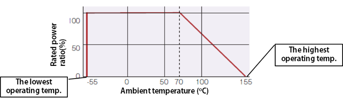
Operating temperature range

The temperature range where, by design, the resistor can be used continuously, defined by the lowest operating temperature and the highest operating temperature.

The lowest operating temperature : The lowest temperature where the resistor can be used continuously.
The highest operating temperature : The highest temperature where the resistor can be used continuously.
The point where derating curve intersects X axis (zero power)

Power derating curve

The curve that shows the operating temperature range and maximum power at each temperature point. This curve is dependent of the different product series.

Technical Information

Technical
Information TOP

How to use chip resistors smartly
  • 1.Basic knowledge of resistors
  • 2.Manufacturing methods and characteristics of thin film resistors
  • 3.Performance characteristics of thin film resistors
  • 4.High precision and high reliability
  • 5.Trimmable chip resistors and altering resistive values
  • 6.Application and recommended usage of thin film chip resistors
  • 7.Application and recommended usage of small high power thin film ship resistors
  • 8.Various methods of current sensing and advantage of current sensing resistors
  • 9.Application and recommended usage of current sensing resistors
Smart usage of
High Frequency
Chip Components
  • 1.Most common high frequency chip: Chip Attenuator
  • 2.Chip Attenuator realized by Thin Film technology
  • 3.Main characteristics of chip attenuators and PAT series
  • 4.Various chip attenuators
  • 5.Chip terminator
Application Information
  • 1. Automotive
  • 2. FA/Robot
  • 3. Measuring Instrument /
    Medical Instrument
  • 4. Consumer equipment
Product Technical Report
  • Standard Specification for surface mount chip resistors
    • Recommended land patterns (soldering footprints)
    • Recommended reflow and flow soldering profile
    • Dimensions of the packaging reel
    • Dimensions of the packaging tape
    Standard Specification for High frequency surface mount components
    • Recommended reflow soldering profile
    • Dimensions of the packaging reel
    • Dimensions of the packaging tape
Technical FAQ
  • High Precision Thin Film Chip Resistors
    • Part numbering
    • Performance characteristics
    • Quality, reliability
    • Mounting, packaging
    Current sensing chip resistors
    • Part numbering
    • Performance characteristics
    • Quality, reliability
    • Mounting, packaging

Contact

Please feel free to contact us about products,
requesting documents and samples.

Contact

  • Sales offices
Page Top

Products

  • New Products
  • Selection guide
  • Product Catalogue

Global Network

  • Word Base
  • Manufacturing Centers
  • Electronic Commerce

Company Profile

About Susumu

  • Principle
  • Susumu Way
  • Profile
  • Locations
  • Organization
  • Company history

Activity Contents

  • Exhibition Activities

Technical Information

How to use chip resistors smartly

  • 1.Basic knowledge of resistors
  • 2.Manufacturing methods and characteristics of thin film resistors
  • 3.Performance characteristics of thin film resistors
  • 4.High precision and high reliability
  • 5.Trimmable chip resistors and altering resistive values
  • 6.Application and recommended usage of thin film chip resistors
  • 7.Application and recommended usage of small high power thin film ship resistors
  • 8.Various methods of current sensing and advantage of current sensing resistors
  • 9.Application and recommended usage of current sensing resistors

Application Information

  • 1.Automotive
  • 2.FA/Robot
  • 3.Measuring Instrument/Medical Instrument
  • 4.Consumer equipment

Standard Specification for surface mount chip resistors

  • Recommended land patterns
  • Recommended reflow and flow soldering profile
  • Dimensions of the packaging reel
  • Dimensions of the packaging tape

Standard Specification for High frequency surface mount components

  • Recommended reflow soldering profile
  • Dimensions of the packaging tape
  • Dimensions of the packaging reel

Smart usage of High Frequency Chip Components

  • 1.Most common high frequency chip: Chip Attenuator
  • 2.Chip Attenuator realized by Thin Film technology
  • 3.Main characteristics of chip attenuators and PAT series
  • 4.Various chip attenuators
  • 5.Chip terminator

Technical FAQ

  • High Precision Thin Film Chip Resistors
  • Current sensing chip resistors

QC and Environmental Activities

  • Susumu's 「ISO Certified」
  • Susumu’s Policy on Conflict Minerals
  • Environmental Policy
  • The materials used in our chip resistors
  • Our Commitment to RoHS/REACH Compliance
  • Designation of lead free products

Privacy Policy | Site map | Contact

Susumu Deutschland GmbH
Susumu Thin Film Specialist and Innovator