|
4-Terminal Current Sensor |
|
|
4-Terminal Current Sensor |
|
| The surface mount-type current sensor with 4 terminals |
|
YDS’s 4-terminal Current
Sensor
enables to surface mount on the ceramic substrate easily. The current
terminals and the sensing are the same, which can be replaceable each
other. It will be much easier to design circuits without a great care
about a precision change generated concerning the position of leads.
Manufacturing resistors in chip type can reduce the cost and they are
available in a wide range of circuits which need even high precision. |
|
… Features … |
|
• High ability to sense the current; ±5% of precision
guaranteed • Small sensing change by temperature change; in resistance to
±50ppm/°C guaranteed • Easy automatic mounting because of surface mount type with
round wrapped electrode; taped serving • Having the current terminals and the sensing independently
enables to realize easy circuit designing with no change of resistance
by connecting points. • High precision and stability because of high precision thin
film and manufacturing methods of it • Having the current terminals and the sensing independently
makes no error by measuring methods and no measuring error before/after
the measurement. • Big overload causes breaking of wire so it is safe for
unexpected overload. • Low price achieved by thin film manufacturing
method |
| …Dimension… |
|
|
(1) Electrode (2) Protection coat (3) Alminum substrate (4) Resistor (5) Marking |
| RL1632L4 |
RL2550L4 |
RL3264L4 | RL3264SW4 | |
| W | 1.6±0.2 | 2.5±0.2 | 3.2±0.2 | 3.2±0.2 |
| L | 3.2±0.2 | 5.0±0.2 | 6.4±0.2 | 6.4±0.2 |
|
T |
0.5±0.15 | 0.5±0.15 | 0.5±0.15 | 0.5±0.2 |
| a | 1.0±0.2 | 1.7±0.2 | 2.1±0.2 | 2.7±0.2 |
| b | 0.55±0.2 | 0.9±0.2 | 1.2±0.2 |
0.4±0.2 |
| …Equivalent Circuit… |
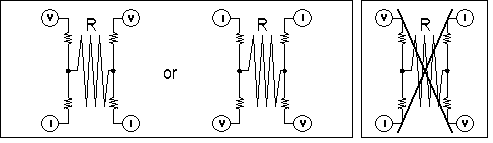 |
|
|
|
| Note: The current terminals and the sensing are the same but please don’t cross lines in case the characteristics might deteriorate. The resistance of this product is called the current sensing resistance and shows the resistance of R in the picture. |
| …Specification… |
|
Item |
RL1632L4 | RL2550L4 | RL3264L4 | RL3264SW |
|
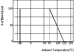
Power
Rating(Derating
Curve???Figure-1) |
0.5W |
0.75W | 1.0W |
2W |
| Resistance
Value for Current Sensing(Note1) |
10m~500mO | 10m~500mO | 10mO~500mO | 1mO~10mO |
|
Resistance
Tolerance |
±0.5%(D) ? ±1.0%(F) | |||
|
Terminal
Resistance (Note2) |
10mO~47mO
:
5mO
or less 50mO~500mO : 20mO or less |
0.5mO or less | ||
| Temperature
Coefficient of Resistance (Note3) |
10~500mO ± 50ppm/°C |
1mO:±300ppm/°C 2~ 4mO:±200ppm/°C 5~10mO:±100ppm/°C |
||
| Maximum
over current |
I=v(20/R) [
A ] (10m
sec. or less) R =
Resistance Value(O) Maximum Current 20A |
I=v(29/R) [
A ] (10m
sec. or less
) R =
Resistance Value(O) Current 23A |
I=v(38/R) [
A ] (10m
sec. or less
) R =
Resistance Value(O) Current 27A |
I=v(150/R) [
A ] (10m
sec. or less
) R =
Resistance Value(O) Current 200A |
| Operating
Temperature Range |
-40~+125°C |
|||
| Rated
Ambient Temperature |
+70°C | |||
 |
Note1: The current sensing resistance shows the resistance generating voltage relative to line current through current terminals. Please pay attention; it is not the resistance between current terminals. Note2:
The terminal resistance shows the resistance of the lines where current
sensing voltage will passing and voltage will be detected. The current
sensing resistance and the terminal resistance show the resistance
between current/ voltage terminals.
|
| …Characteristics… |
???
|
Item |
Conditions |
Specification |
|
Short Time Over Load |
Voltage
of 1.5 times the rated voltage shall be applied for 5s. |
±(0.5%
+0.0005 ohm) |
|
Load life |
Rated
voltage for 90min followed by a pause of 30min at a temperature of 70±3°C.
Cycles shall be repeated for 1000H. |
±(0.5%
+0.0005 ohm) |
|
Moisture Load life |
Rated
voltage for 90min followed by a pause of 30min at a temperature of 60±2°C
with relative humidity of 90~95%. Cycles shall be repeated for 1000h. |
±(0.5%
+0.0005 ohm) |
|
Temperature Cycle |
[-40°C 30min ~ R.T. 3min ~ +125°C30min
~ R.T. 3min ] 5continuous
cycles. |
±(0.5%
+0.0005 ohm) |
|
Soldering Heating |
Dipped
into solder for 10±1sec at
260±5°C |
±(0.5%
+0.0005 ohm) |
|
Substrate Bending |
Between
fulcrums :90mm Bend
width
: 2mm Glass-epoxy
board t=1.6mm |
±(0.5%
+0.0005 ohm) |
|
Solderability |
Dipped
into solder for 3±0.5sec
at 235±5°C |
95%
or more of the substrate surface should be wet. |
?
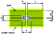
| … Recommended Land Pattern… |
|
|
(mm) |
L |
W |
A |
B |
C |
|
|
|
RL1632L4 |
8.0 |
3.5 |
1.0 |
0.3 |
4.5 |
2.5 |
||
|
RL2550L4 |
12.0 |
5.5 |
1.4 |
0.5 |
6.5 |
3.6 |
||
|
RL3264L4 |
15.0 |
7.0 |
2.0 |
0.6 |
8.5 |
4.4 |
||
|
RL3264SW4 |
20.0 |
20.0 |
2.2 |
1.0 |
5.0 |
7.6 |
<Packaging>
For further information of packaging click!
<4 The way to use 4-terminal current sensor>
4For further information of the example of use of 4-terminal current sensor click!
|
Yokohama Densi Seiko Co., Ltd. |