|
4-Terminal
Current Sensor |
The
operation of 4-terminal current sensor
4-terminal
current sensor is the element which can convert current into voltage in a
circuit.
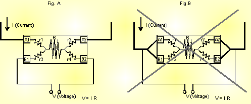
A
circuit is opened due to connecting to the current terminals (A1 and A2 in the
figure A). The current goes through the terminal resistor (r1), the current
sensing resistor (R) and another terminal resistor (r2) in the left picture.
Then, the same voltage generates between terminal B1 and terminal B2 as well as
at the both ends of the current sensing resistor. This voltage enables to detect
the flowing current.
current
[I] = voltage [V] / current sensing resistance [R]
 Though voltage generates at the both ends of terminal resistors in a
current circuit, it is not included in a voltage sensing circuit so it need not
be considered. Each terminal resistor (r3 and r4) is quite small related to
impedance in a voltage sensing circuit, so it is possible to measure the current
accurately without any consideration about resistance.
|
Yokohama Densi Seiko Co., Ltd.
Last Update 03/04/04
|
 Though voltage generates at the both ends of terminal resistors in a
current circuit, it is not included in a voltage sensing circuit so it need not
be considered. Each terminal resistor (r3 and r4) is quite small related to
impedance in a voltage sensing circuit, so it is possible to measure the current
accurately without any consideration about resistance.